Fig 5.2.1 Device Table Window

Fig 5.2.1 Device Table Window
File Name : File name of "Device Table" to save.
Frontend
Receiver : Select a receiver from the list shown by pushing the right buttons.
Track Frequency : Tracking frequency.
Sideband : Only DSB mode is available.
BackendType : Type of backend. Default is DASBOX.
Channel Begin-End : Begin and end channel numbers which you use.
Reference Channel : Channel number of the reference signal for lock-in procedure. Default is 3.
Monitor Channel : Channel number of sky monitor. Default is 4.
Channel Notes : You can write a comment for each channel. For use, Channel Notes Window appears.
Option : You can change parameters of the backend (In general, you don't have to change them). For use, Option Window appears to set parameters.
Switching Mode :
Beam switch : Beam Switch Window appears to set parameters. In general, you don't have to change them.
none : Default. DC measurement.

Chan (1) - (16) : Enter comment for each channel.
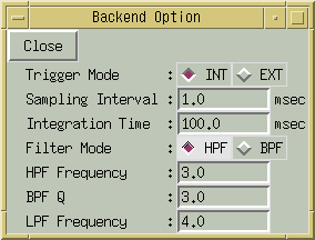
Trigger Mode : Select INT (Internal) or EXT (External). Default is INT.
Sampling Interval : Interval of data sampling by A/D convertor. Default is 1 msec.
Integration Time : Integration time. Default is 100 msec.
Filter Mode : Select HPF (High Pass Filter) or BPF (Band Pass Filter). Default is HPF.
HPF Frequency : Cutoff freuency of high pass filter. Default is 3 Hz. For BPF, this is the center frequency of band pass filter.
BPF Q : Q value (Q = f/△f) of band pass filter. Default is 3.
LPF Frequency : Cutoff frequency of low pass filter. Default is 4.
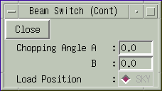
Chopping Angle A, B: Default is 0.0.
Load Position : Load position during observation.
SKY : Default.