 button
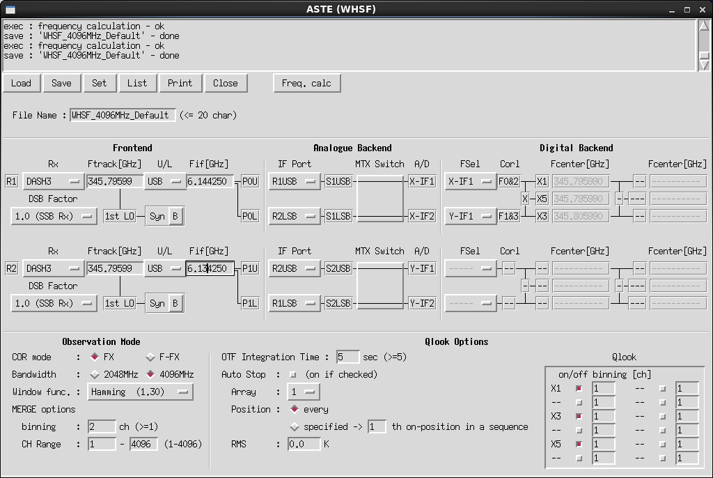
You can use the FX correlation mode for wide-band observations and the F-FX correlation mode for high-dispersion observations. For details, please see WHSF Status Report.
- COR mode : Correlation mode
- Choose either FX or F-FX. From 2014, only FX is available.
- Bandwidth :
- Choose either 2048MHz or 4096MHz.
- Window func. : FFT window function
- Choose a window function from a pull-down menu. Effective frequency resolution is multiplied by a factor of 0.886 (None) / 1.44 (Hanning) / 1.30 (Hamming) / 1.64 (Blackman). Either "Hanning" or "Hamming" is strongly recommended.
- MERGE options
- These options allow you to reduce the volume of output data. Number of channels of output data is limited to less or equal to 2048. At present, the following default settings for "MERGE options" can be used. Do not set other parameters.
- binning : Number of binding channels. Default is "2" (2ch binning).
- CH Range : Channel range you want to use. Default is "1 - 4096" (all channels).
Currently, both DAHS345 and BAND8 are available..
- Rx : Receiver type
- Choose a receiver from a pull-down menu. Set same parameters for both R1 and R2 in 2015 season.
- Ftrack : Tracking frequency
- You can define up to the 6th decimal place. Set same parameters for both R1 and R2 in 2015 season.
- For a high-z object, enter the frequency corrected for Doppler shift. In that case, the velocity of the object defined in your "Source Table" should be 0 [km/s].
- U/L : Sideband type for frequency tracking
- Choose either upper sideband (USB) or lower sideband (LSB).
- Fif : IF frequency
- Ftrack is converted to Fif by 1st LO. You can select Fif in the range of 4.096-6.144 GHz (for 2GHz bandwidth mode) / 4.096-8.192 GHz (for 4GHz bandwidth mode).
- Syn : Select synthesizer used as 1st LO
RX Synth DASH3 B BAND8 B
- DSB Factor : Scaling factor of intensity
- Choose either 1.0 (SSB Rx) (= Default for DASH3/BAND8) or 2.0 (DSB Rx).
- IF Port : Input IF signal into Switch box
- Choose input IFs from pull-down menus.
- At present, you should not changed the default setting of the following "Examples of Device Table".
- MTX Switch : Input-Output selecting switch
- Decide the flow of input IF signals into four A/D Convertors (X-IF1, X-IF2, Y-IF1, Y-IF2) from pull-down menus.
Correlators process IF signals from analogue backend.
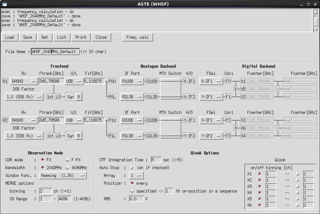
You can choose up to 2 input IF signals in 4096MHz-bandwidth mode, and up to 4 input IF signals in 4096MHz-bandwidth mode.
In F-FX mode, IF signals are processed into 512ch at 1st stage, then selected channels are further processed into 2048ch at 2nd stage.
- FSel : Selection of IFs into correlators
- Choose signals from A/D Convertors into correlators (F0, F1, F2, F3).
- In 4096MHz-bandwidth mode, F0 & F2, F1 & F3 process the same signals. You can choose either X-IF1 or X-IF2 from X system, and Y-IF1 or Y-IF2 from Y system.
- In 2048MHz-bandwidth mode, you can choose any signals from A/D Convertors (X-IF1, X-IF2, Y-IF1, Y-IF2) into F0, F1, F2 and F3.
- Fcenter : Center frequency of arrays
- Left columun shows center frequencies of arrays at 1st stage. These frequencies are calculated by "Frequency calculation program" by pushing
- Right column shows center frequencies of arrays at 2nd stage only in F-FX mode.
- In F-FX mode, you can further process any consecutive 8 channels of each array at 1st stage. Set center frequencies of arrays at 2nd stage within the bandwidth.
- Check the input parameters by pushing
* AC: Auto Correlation. CC: Cross Correlation.
Table 1. Array name and Correlation Correlator Array name Correlation FX 4G-BW FX 2G-BW FFX 4G-BW FFX 2G-BW 1st X1 AC F0&F2 F0 F0&F2 F0 X2 AC - F1 - F1 X3 AC F1&F3 F2 F1&F3 F2 X4 AC - F3 - F3 X5 CC F1*F2 F1*F2 F1*F2 F1*F2 X6 CC - F3*F4 - F3*F4 2nd X7 AC - - F0&F2 F0 X8 AC - - - F1 X9 AC - - F1&F3 F2 X10 AC - - - F3 X11 CC - - F1*F2 F1*F2 X12 CC - - - F3*F4
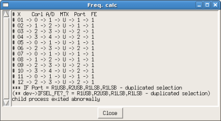
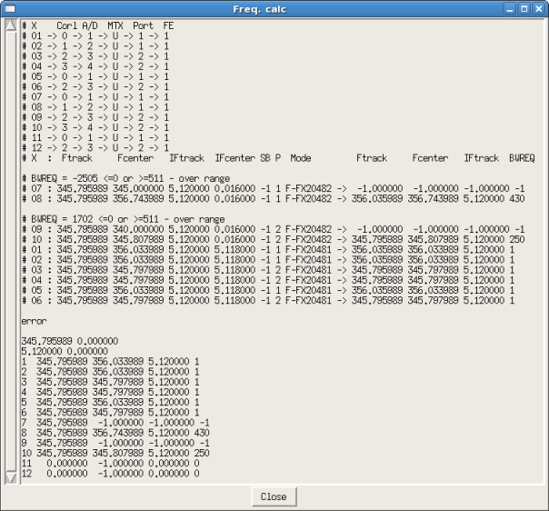
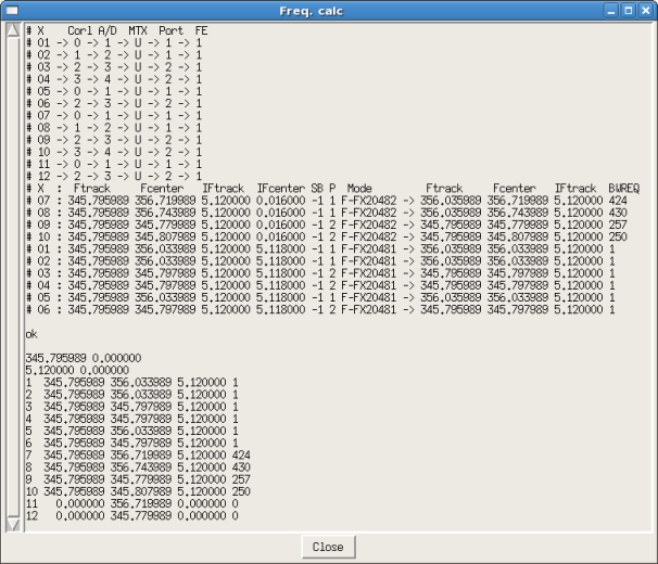
This program calculates center frequencies (Fcenter) of arrays based on input parameters.
button, Fcenters are set to the device table. The details of the calculation display in a pop-up window.
- OTF Integration Time :
- Integration time of a spectrum displayed on Qlook window in OTF mode.
- Auto Stop :
- If checked, observation automatically stops when a rms noise level of an array of backend falls below a threshold you set in RMS.
- Array : Array of backend where the noise level is checked
- Select an array between X1 and X12.
- Position : On-point position where noise level is checked
- If you want to check the noise level at all on-positions, check "every". If you want to check it at a particular position, check "specified" and enter the on-position number in the sequence of observation.
- RMS : Threshold of rms noise level
- Qlook :
- on/off :
- If checked, you can monitor spectra of the arrays on Qlook window and can analyze the data with quick merge program.
- binning :
- Number of binning channels. Default is "1".
- You can also enter the other value for channel binning in Qlook. For example, when you set 2 in Device Table and 3 in Qlook, the number of binning channels is 6 (= 2 x 3).